


GWER-2500 EARTH RESISTANCE TESTER
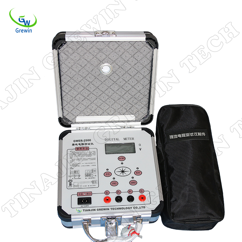
GWER-2500 EARTH RESISTANCE TESTER
1.Introduction
The tester abandons the traditional way of making power by artificial, uses advanced large scale integrated circuits,applies DC / AC transformation technology ,makes three side buttons, four-terminal measurement button to combine into a model of the new grounding resistance measuring instrument.
The principle of the tester is to make DC into AC low-frequency constant current by the DC / AC converter inside, through the auxiliary grounding electrode C and E composition of the measured object circuit to generate AC voltage drop measured object, sent by the auxiliary grounding electrode P AC amplifier and then displayed through the detector head into the table. With magnification switch, available in three different capacity limits: 0 ~ 2Ω, 0 ~ 20Ω, 0 ~ 200Ω.
2. Application
The tester applies post and telecommunications, railway, telecommunications, mining and other sectors of the grounding resistance measurement of the various devices and the measurement of low resistance of the conductor resistance; this tester can also measure soil resistivity and ground voltage.
Main features
• the structure of high strength aluminum alloy case, the circuit to prevent the frequency, radio frequency interference detection method using phase-locked loop tracking and accompanied by synchronous switched capacitor filter, the instrument has good anti-jamming capability.
• use of DC / AC technology will transform the low-frequency constant DC current into AC for the measurement.
• Allow auxiliary grounding resistance in the 0 ~ 2KΩ (RC), 0 ~ 40KΩ (RP) between the change not affect measurement results.
• No manual adjustment of the instrument balance, 3 (1 / 2)-bit LCD display, in addition to resistance measurement, it can also measure low resistance conductor resistance, soil resistivity and the AC ground voltage.
• Should the test loop unreasonable header displays "1" overflow, consistent with conventional measurement practices.
4.Technique Data
1) Operating Conditions
Ambient temperature: 0 ℃ ~ +45 ℃
Relative humidity: ≤ 85% RH
2) Measuring range and the constant value (RMS)
Resistance: 0 ~ 2Ω (10mA), 2 ~ 20Ω (10mA), 20 ~ 200Ω (1mA)
Voltage: AC 0 ~ 20V
3) Measurement accuracy and resolution
Accuracy: 0 ~ 0.2Ω ≤ ± 3% ± 1d
0.2Ω ~ 200Ω ≤ ± 1.5% ± 1d
1 ~ 20V ≤ ± 3% ± 1d
Resolution: 0.001Ω, 0.01Ω, 0.1Ω, 0.01V
4) Errors caused by auxiliary earth resistance and ground voltage measurement
• Allow auxiliary grounding resistance RC (C1 and C2 between)
0 ~ 2Ω, 2 ~ 20Ω ≤ 1KΩ
20 ~ 200Ω ≤ 2KΩ
RP (P1 and P2 between) <40KΩ error ≤ ± 5%
• Allow to voltage (rms frequency) ≤ 5V error ≤ ± 5%
5) Power
maximum power dissipation≤ 2W
DC: 8 × 1.5V (AA, R6) Battery
AC: 220V/50Hz
6) Size and weight
Host Size: 220mm × 200mm × 105mm
Host Weight: ≤ 1.4kg

Mail: salesmanager@grewin-tech.com TEL:86-22-84943756 Skype:lialice99 WhatsApp/Wechat:+86-13072088960
ADD:RM1013 2#Building MeiNian Plaza DongTing Road HeXi Distr,300222 Tianjin China.
| 
| 
|